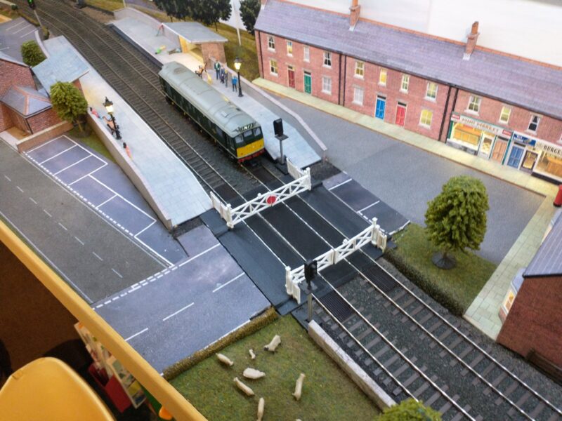
Just before lockdown, I took home one of the club model railway boards that I had been working on. As the club was to be closed, I also took a selection of club materials to finish the scenery in all the spare time I (didn’t) have.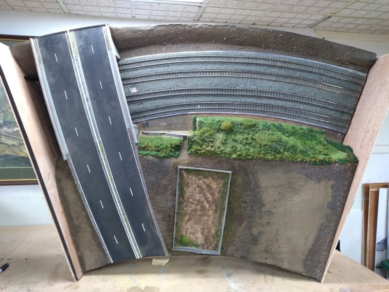
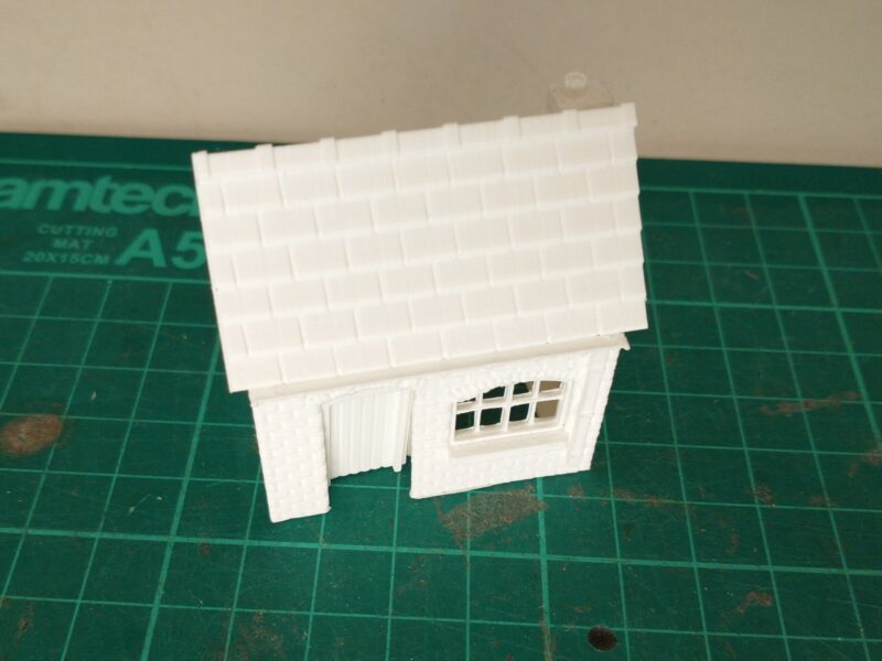
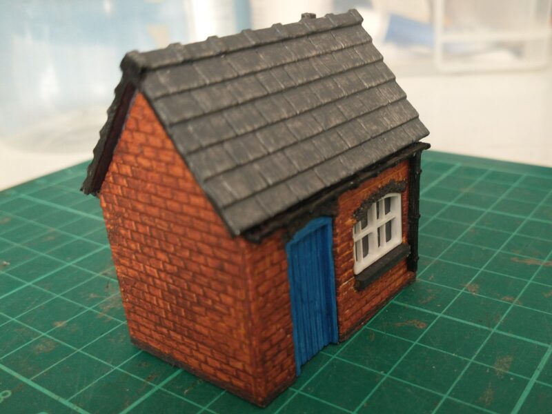
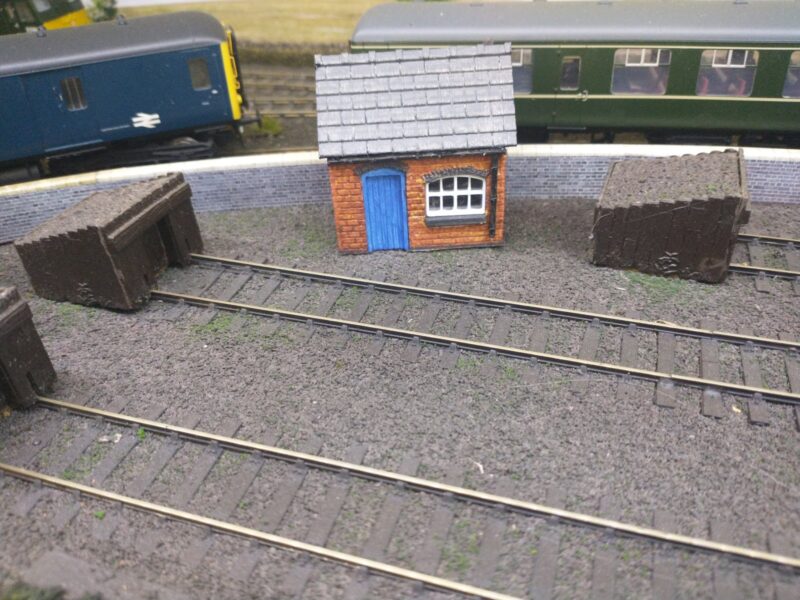
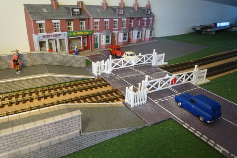
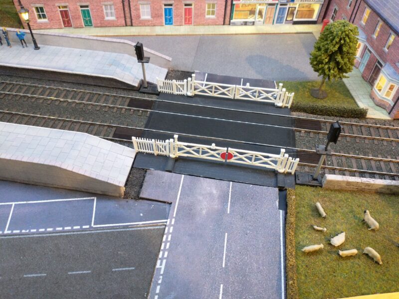
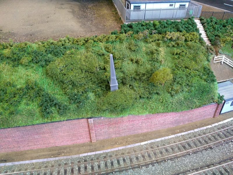
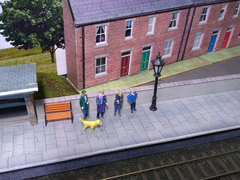
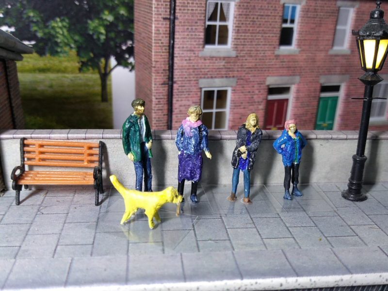
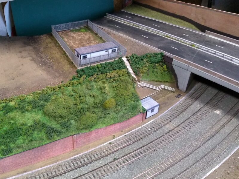
The first job was to add some buildings and walls, and tidy up the grassed bank and steps. I also used the club Static Grass Applicator to add some “grass” behind the road:
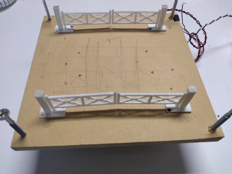
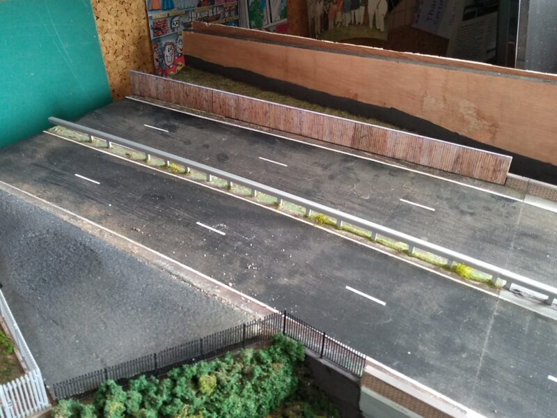
I also added a couple of fences:
The next job was to apply “grass” to the rest of the board. I was unconvinced that the club applicator was working properly, and another one that I borrowed didn’t seem to be much better. These work by generating a very high voltage, and using static electricity to attract the “grass” onto a layer of glue, the idea being that most of it sticks up rather than laying flat.
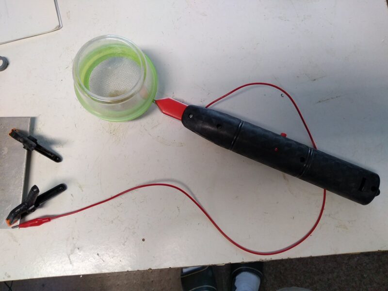
In the end, I tried adding a metal tea strainer to the club applicator – this looks rather unprofessional, but worked much better:
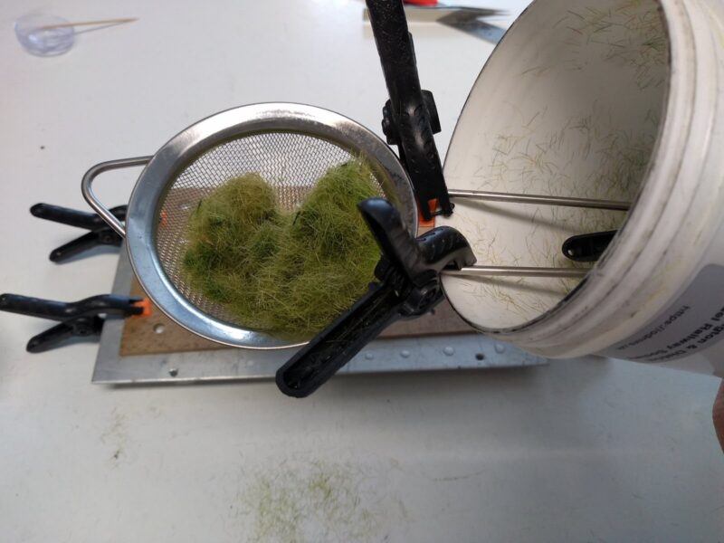
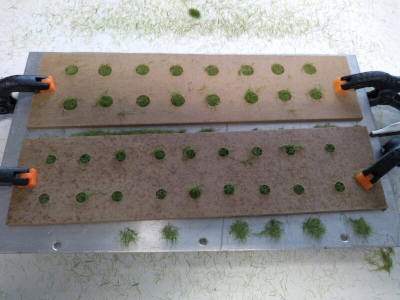
I then used this to make some grass “clumps”. First off, a couple of bits of wood with holes in are clamped to an aluminium sheet, then small dobs of PVA glue added in each hole with the cocktail stick:
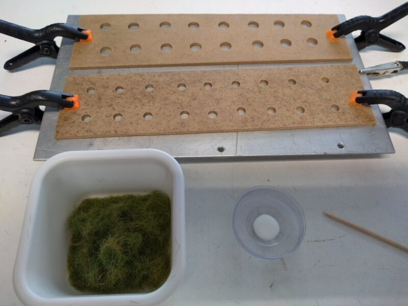
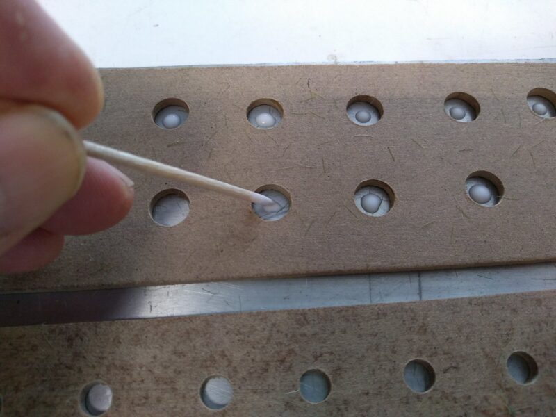
The grass is loaded into the tea strainer and the electricity switched on:
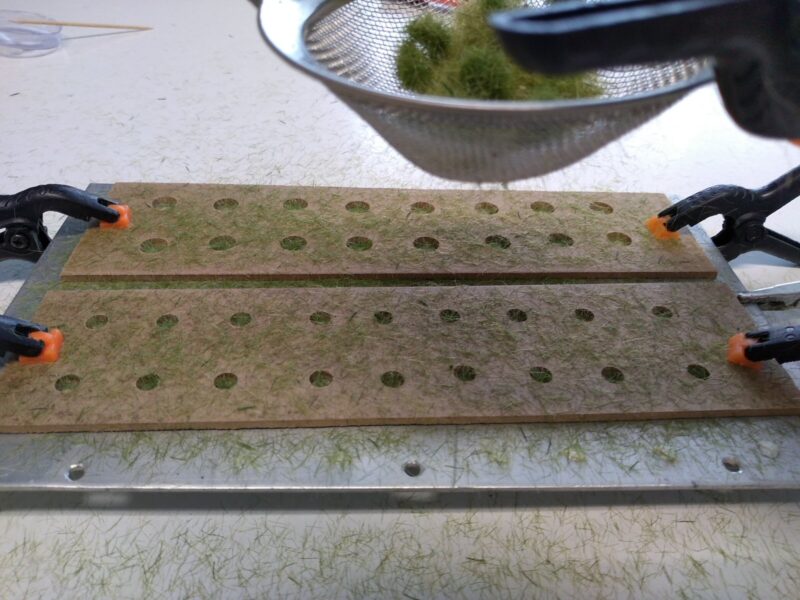
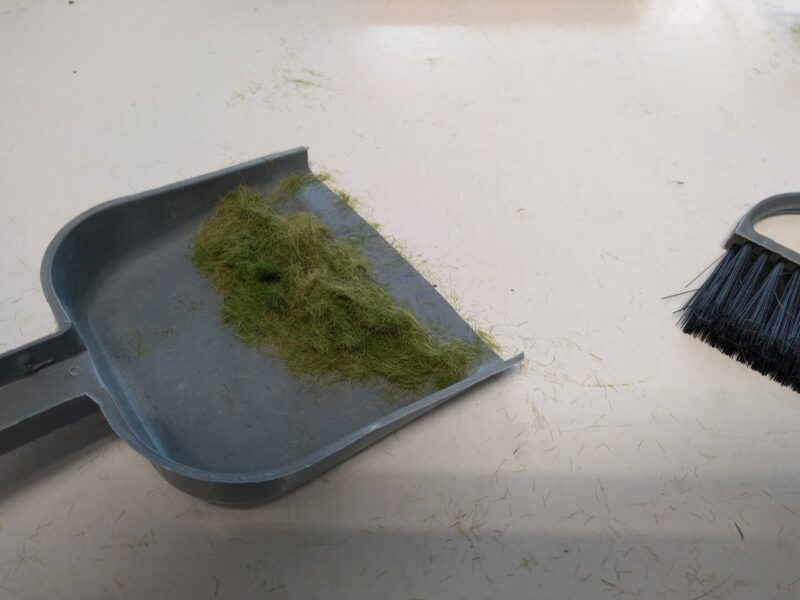
When the strainer is shaken, the fibres are attracted to the metal sheet and the holes gradually filled up. The fibres also go everywhere else of course, so need to be swept up to be reused:
Once the excess is shaken off, you can see the filled holes:
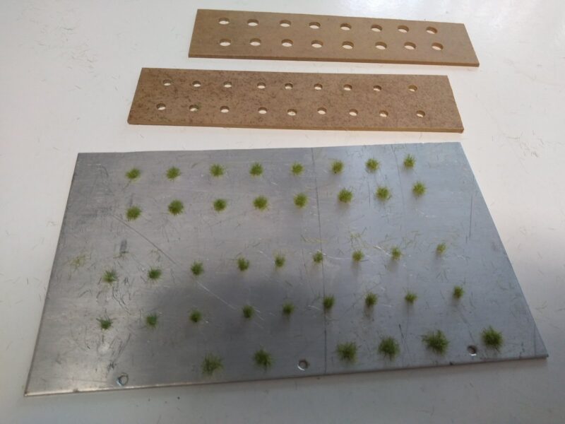
This is repeated a few times with different ‘grass’, then the wood frames are carefully removed, leaving the clumps on the metal sheet:
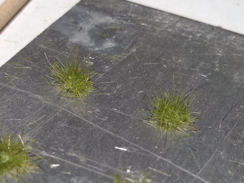
And in close up:
Once the glue has dried, these can be popped off the sheet and glued into place on the layout.
Part 2
I then decided to buy my own Static Grass Applicator so that I could use it on my layout. I found a ‘tea strainer’ sort for sale, but it didn’t seem to work very well. A bit of research revealed that it was a modified electric fly swatter, and didn’t produce nearly enough voltage to move the fibres. With help from a colleague, I rebuilt the circuitry inside to double the voltage output to -3.4KV, and it now works far better than the club one!
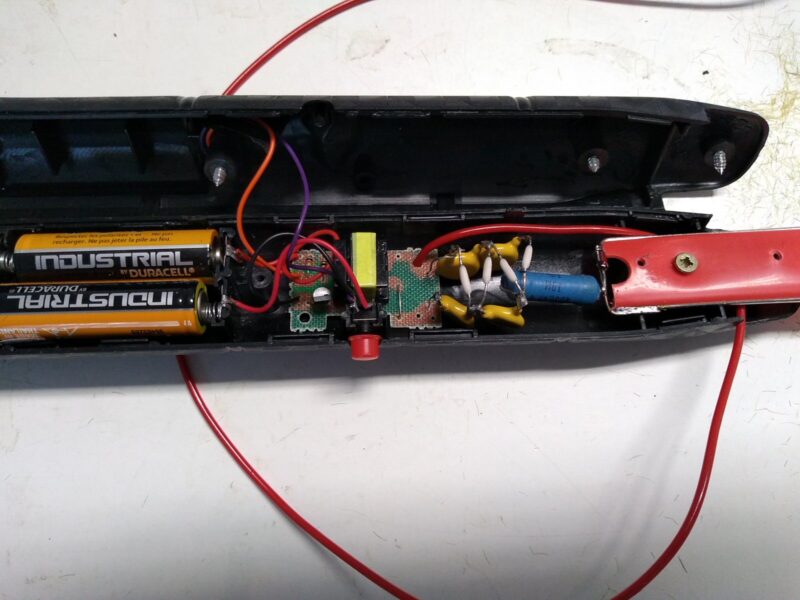
The cover on the tea strainer is good as it stops the fibres flying out of the top of the tea strainer:
Now all the bits are in place, all I need to do is finish the club layout board!


