Things have been happening “behind the scenes” on the railway…
One of my long term plans was to replace the current track with more realistic looking track. Last year, I was fortunate to acquire a selection of hand made points which had been removed from another layout: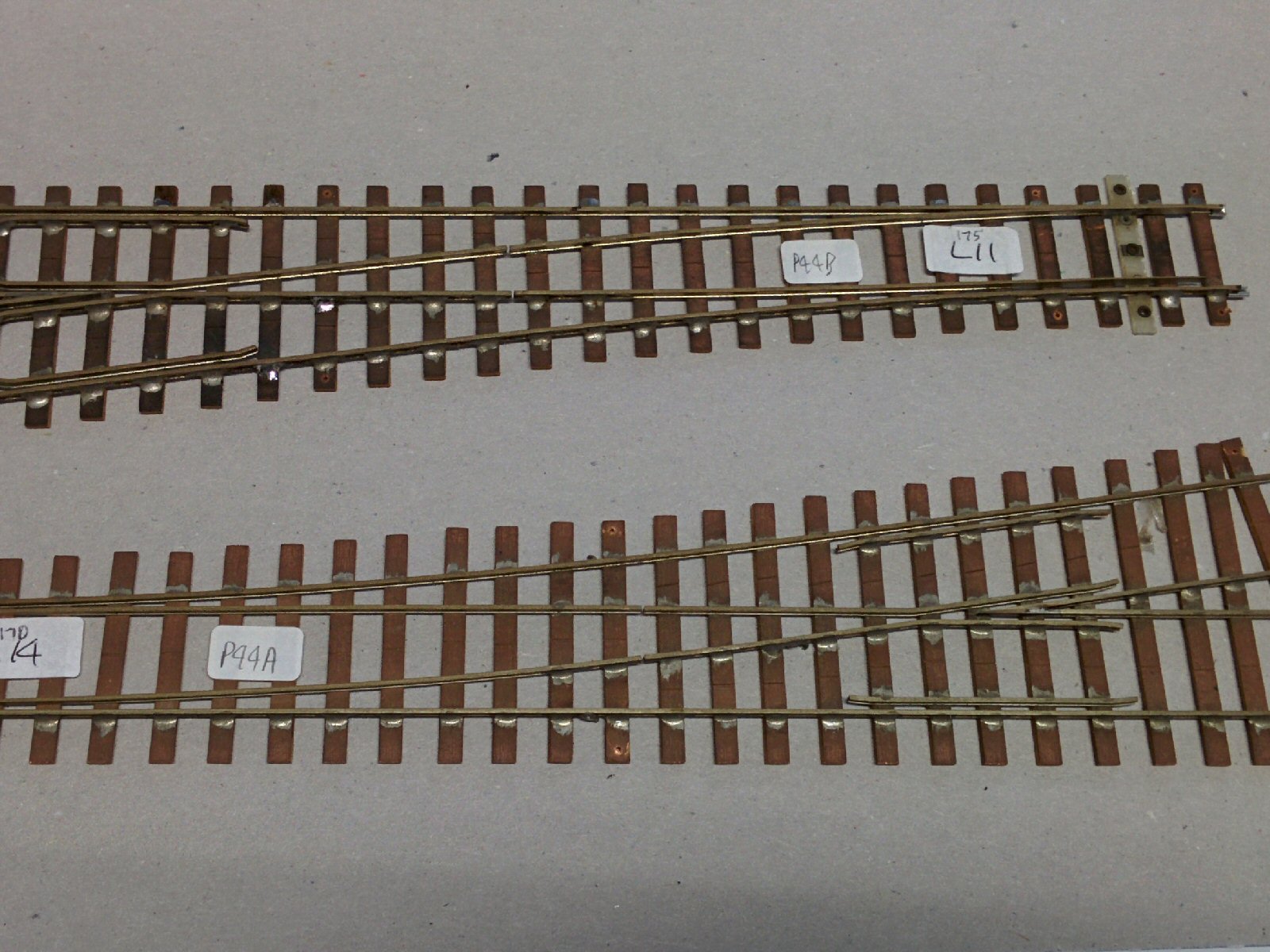
These points are beautifully built (far better than I could do), but there were not enough of the right sort of points for my layout, so after buying a couple of “kits”, embarked on making some myself.
The first stage is to fix the printed template to a bit of board, and cut strips of copper clad board to make the “sleepers”. These are stuck on with double sided tape to hold them in position: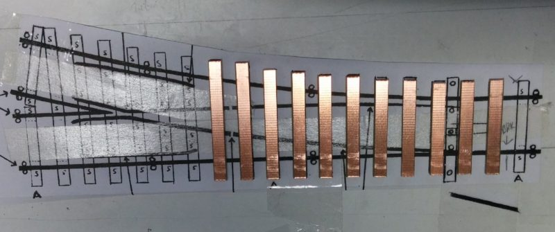
The far right sleeper has been left off as this point needs to be installed very close to another point: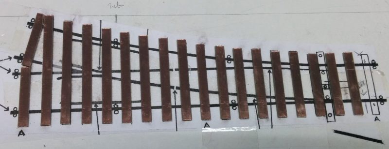
To get the first rail straight (and vertical), I used some aluminium angle as a reference:
The rail is soldered on to the sleepers:
This rail acts as a reference for the other rails. Note the two roller gauges on the left – these are used to get the right distance between the rails.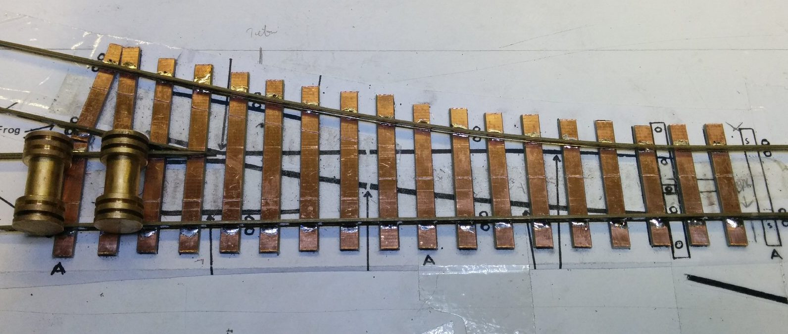
This picture shows all the fixed rails fitted: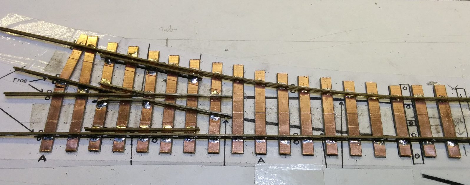
And finally, the point blades are fitted, soldered to a “tie bar” on the right hand side. The tie bar will be moved by a motor, causing the point blades to direct the train in the correct direction.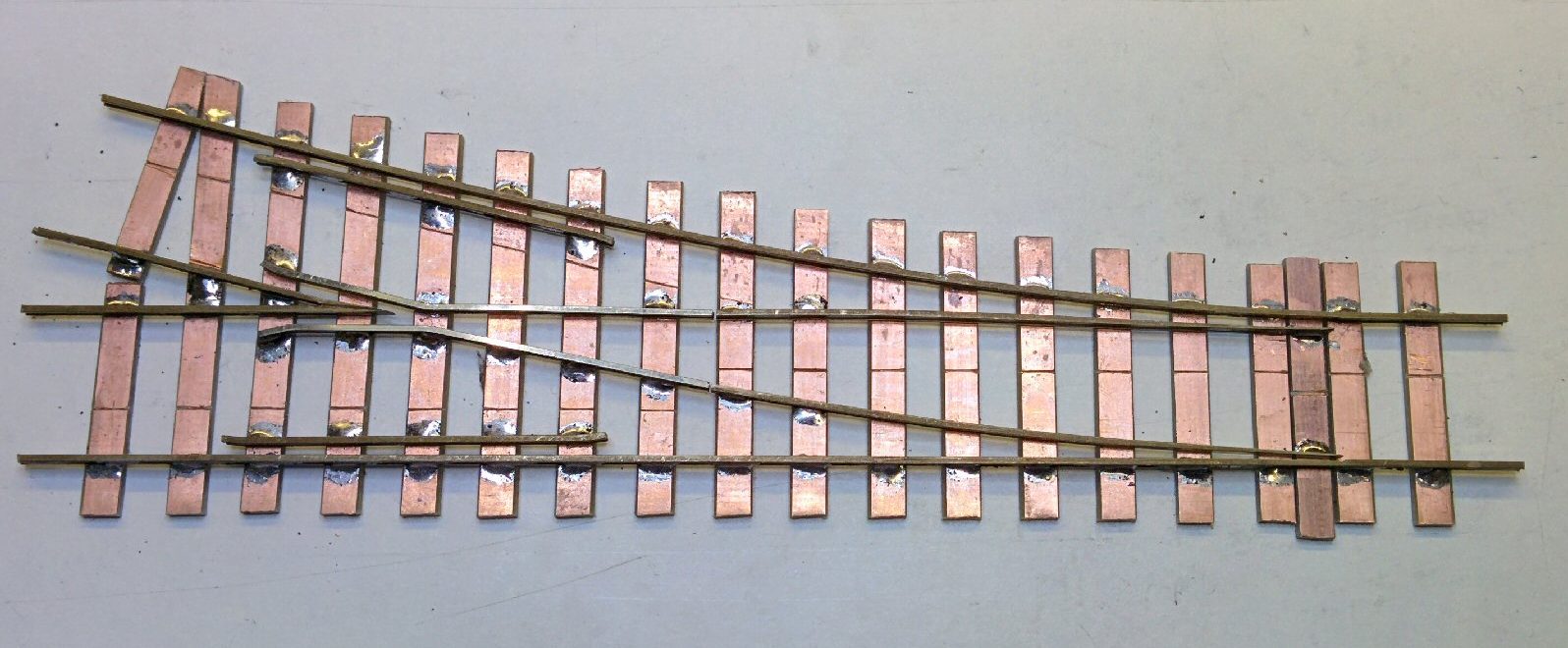
This looks a bit untidy, but once most of it is hidden under paint and ballast, it’ll be fine!