For our club exhibition layout, there was a requirement that a short or fault in one section of the layout didn’t stop the entire layout operating. Initially, this would be done by having four power districts, each fed from their own booster.
As this would have increased the cabling, connectors and overall cost of the layout, alternative approaches were investigated, initially using the old trick of wiring a 12V lamp in series with each track feed.

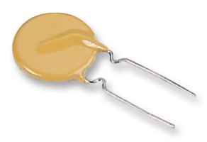
However, with modern components, a simpler approach is possible using PTC (Positive Temperature Coefficient) resettable fuses. They are sometimes called a Polyfuse or a Polyswitch.
These are low cost (20p) two terminal devices whose resistance increases dramatically as their temperature rises.
This has the effect of limiting the current under short circuit conditions. When the short is removed and the device is allowed to cool down, normal operation resumes.
A typical device, which we use for our 00 gauge layout, is the Bourns MF-RO50 device. The ‘cold’ resistance of this device is around 0.5 ohm, and the ‘tripped’ current when a short occurs is around 0.5A.
Other gauge layouts would need larger (or smaller devices).
These devices are also very useful for protecting various DC power feeds from short circuits.
Typical Connection

This shows the basic track connections for the PTC fuses. Within reason, the shorter each track section, the more protection will be provided.
MERG NB1B Booster Modification
When a short occurs, the initial current is limited by the booster, the layout wiring and the cold resistance of the PTC fuse (around 0.5 ohm for the MF-RO50). This current (peaking around 8A) is sufficient to trip an unmodified MERG NB1B booster, which defeats the whole point of the block protection.
However, if C5 on the NB1B is increased to around 220nF, LK2 is removed and the booster is set for 10A output, a short on any individual track will not cause the booster to trip. For this to work reliably, the power supply feeding the booster also needs to be capable of delivering the maximum short circuit current, albeit only for periods.
The NB1B current limiter (when mounted on a heatsink) is more than capable of limiting the current for the 200mS or so that the PTC fuse takes to warm up.
Monitoring
If an indication of a fault is required, a LED (with a diode and series resistor) can be wired across each PTC fuse. This will only be lit when a short or other fault occurs.
The other method is to touch the PTC fuse – it will be too hot to touch under sustained fault conditions.
Testing
Whilst in theory the current available from the MF-RO50 is insufficient to allow any DCC 00 gauge loco to operate, in reality, it works with the largest modern 00 loco we have tried – even with the sound wound up to the maximum. Empirical tests would suggest that this is because the loco current peaks are too short to increase the PTC temperature significantly.
Long multiple units are not a problem for our layout either, as the maximum length of track in any protected section is less than 4 feet and the power for a long train will be taken from multiple sections.
Note that if a short is sustained for a long period of time, then it can be up to 30 seconds before the device cools down enough to restore full power.

