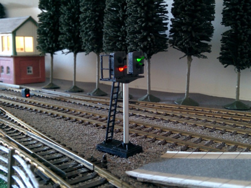
There are many options available for colour light signals, however, many of the commercial solutions are let down by using LEDs that are either oversize or have unrealistic colours.
After investigating a number of solutions, I’ve found a simple method of fitting LEDs that look much more like real signals into a Train-Tech SK1 kit. The SK1 kits cost around £5, the LEDs and other bits around £1.
Train-Tech do sell kits with LEDs already fitted to a PCB, but the size and colours of these are poor. In addition, the PCB sticks a long way below the layout, making them difficult to use without modifications on all but the deepest base boards.
LEDs
After much research, I’ve found the OSRAM “TOPLED BLACK” range to be the best currently available at a sensible price. This is a surface mount LED, but the pads are large enough to solder wires directly to them. They are primarily designed to be stacked together for LED message boards.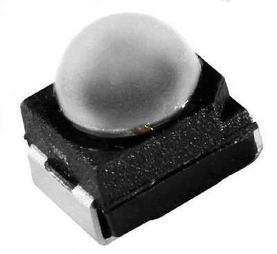 The front dome is the right diameter for a 00 signal, and “True Green” LEDs are available, which are a much more realistic colour than standard (‘yellowish’) green LEDs.
| Colour |
Part Number |
Wavelength |
Resistor |
| Red |
LRT64F-BADA-1 |
625nM |
22K |
| Yellow |
LYT64F-BBDA-35-1 |
590nM |
10K |
| True Green |
LTT64G-DAFA-29 |
528nM |
150K |
You will find similar part numbers listed; these generally refer to devices with different average light intensities.
The resistor values shown, when used with a 5V supply, give an appropriate light output for a layout, with a reasonably similar intensity for each of the different colours. The 150K resistor for the ‘True Green’ LED is not a misprint; these LEDs are VERY efficient. Use higher values for a 12V supply; lower values for a multiplexed drive.
RS Components stock these LEDs, though only sell them in multiples of 25.
Construction
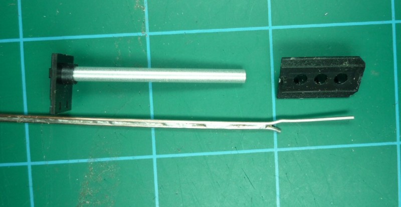
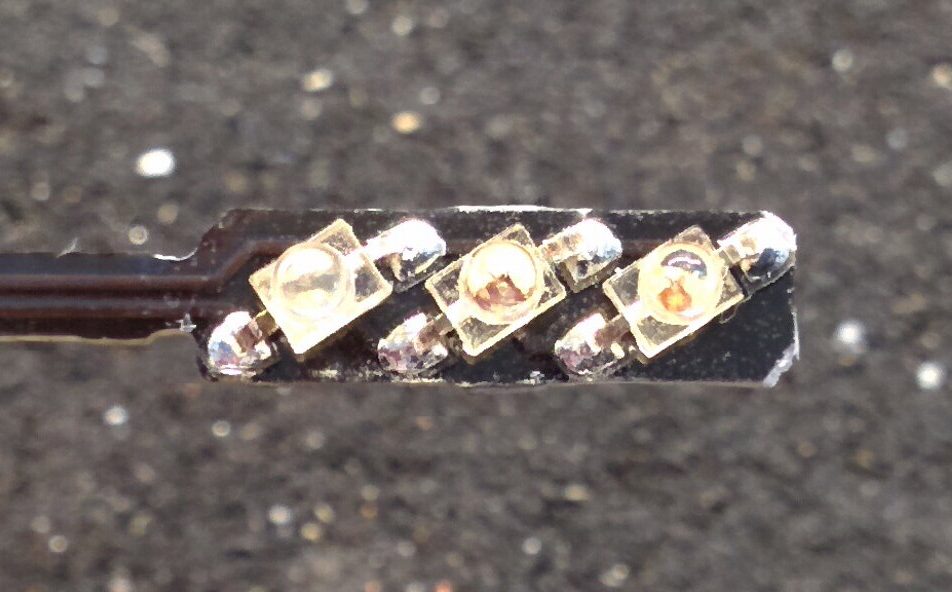
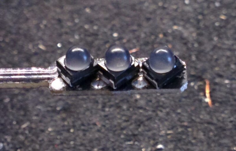
Solder a couple of lengths of 0.5mm tinned copper wire together, and bend them as shown.
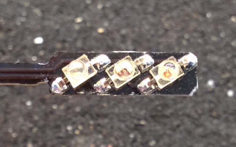
Fit the LEDs (in the correct order and polarity) into the back of the signal. A bit of glue can help to stop them flying away. A 5V power supply with a 4K7 resistor in series helps to identify the colour and polarity of each LED. Solder one arm of the wire to the negative LED pads, taking care that the ‘Y’ of the wire is in the right place for the back to fit,. Make sure it does not touch the other pad of the red LED:

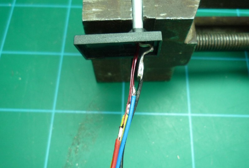
Now solder some very thin insulated wire to each of the positive pads:

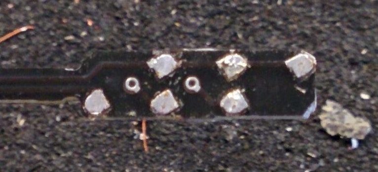
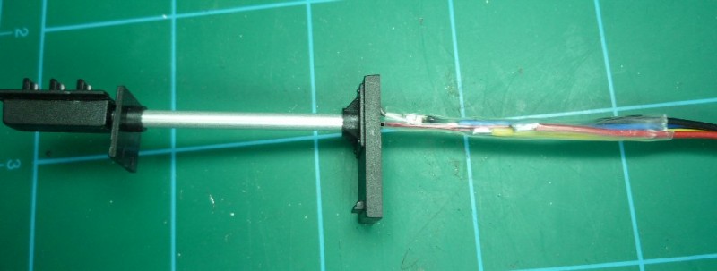
Ensure the signal head base can slide over the wires, and check that the signal head back still fits. Don’t glue anything at this stage, but test it works electrically. Slide a piece of heatshrink sleeving over the tinned copper wire so that the post doesn’t become ‘live’, then slide the post up to the signal head:
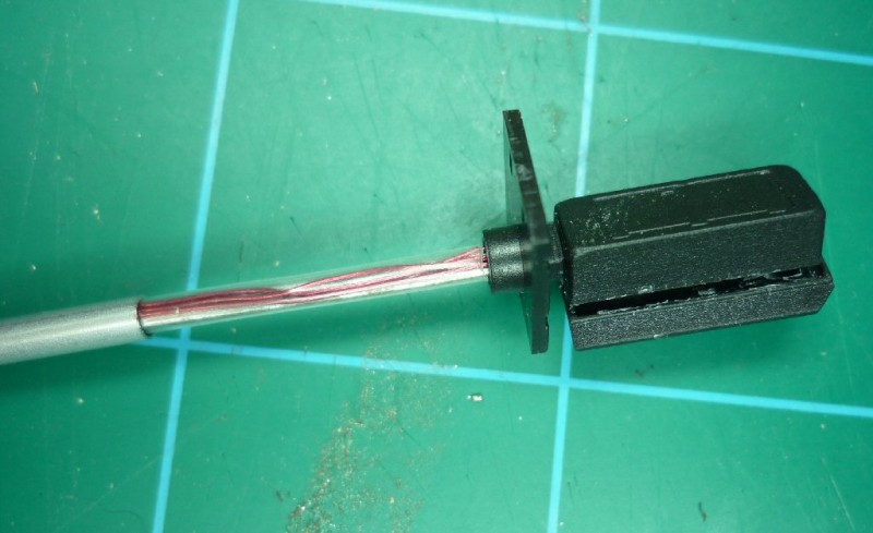
The base can then be fitted. Put a kink in the thick wire to stop the signal coming apart, and solder wires to the various connections; I stagger the connections so they won’t short:

Cover the connections with another piece of heatshrink sleeving, and glue the signal head back and front together.
The signal is now ready for fitting to the layout. The ladders and other parts are best fitted after the main signal is installed. The connections and wire underneath can be gently bent to suit.
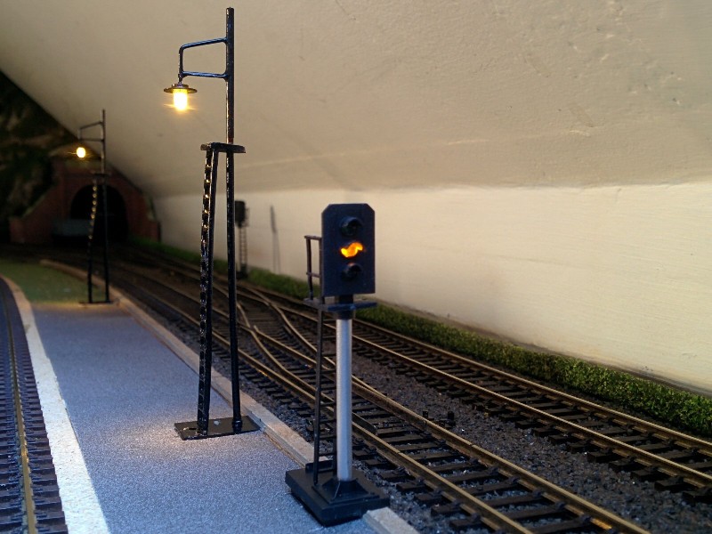
Whilst this example shows a three aspect signal, the process is the same for two or four aspect signals.
Ready Made Signals
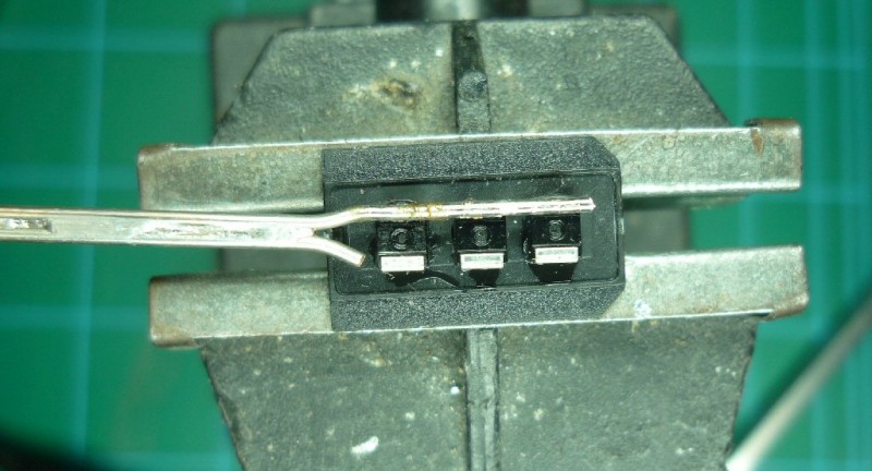
To change the LEDs on ready made Train-Tech signals, first carefully remove the existing LEDs from the PCB:
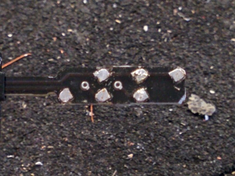
Clean the old solder from the pads, but put a fresh blob of solder on the three top (common) pads. Then tack the new LEDs onto the common pads, checking that:
- They’re flat on the PCB.
- They’re the right way round.
- They’re the right colour.
- That the cover still fits.
When you’re sure everything is OK, solder the remaining legs to the pads.
I also used this method to replace the LEDs on a SK7 Dual Head signal kit.