New Tracks Laid

Finally, after what seems like ages, all the new track has been laid, positioned properly and glued to the baseboards.


The curve at this end of the platforms was quite critical to get right, and the signal you see on the left had to be moved out so nothing hit it…

This will all need ballasting in due course.

The village has been tidied up but more will need to be done once the level crossing is finished and the platforms rebuilt.


Country End Rebuild

New points for the country end of the layout have been made from the reclaimed points:
and point motors added underneath:
The old track and points have been stripped from the country end of the layout:
Once the holes for the new points were cut (a messy job!), the area was sprayed with primer and the new points laid:
Unfortunately, a couple of point motors ended up across a strut, and an extension arm had to be installed to connect the motor to the point blade (on the right in this photo):

Point 21a

As time permits, I’ve been mounting and fitting points to the Goods Yard area. However, there was a problem with the last point to be made – the motor had to go where there was a strut and a bunch of wires under the layout.

So a bit of inventive thinking came up with this:

The motor drives the right hand side of the shiny copperclad bar, which pivots on the bolt in the middle, and the tie bar is driven via a pin on the left hand side.

So the left part will fit in a channel in the 9mm baseboard.

This is the top of the point, ready for installing in the layout:

You can see the pivot bolt; this will eventually be covered by ballast.

Corner Points Fitted

The old corner points and associated track have been cleared:

Holes were cut in the baseboard, and the new points (see Corner Points Construction to see how they’re made) were then fitted:

To the right of this picture, you can see a short adaptor which has been temporarily installed to convert the new, finer scale, track to the old track:

And then finally, the associated track was fitted. This is glued down with a dilute Copydex mixture, which will hold the track in place prior to it being ballasted:

The old trackbed in the front of this picture will become a road.

Corner Points

The Corner Points (61 & 62) have now been assembled from reclaimed handmade points and point motors fitted. These will go in the corner of the layout near the main station.

I’ve improved and simplified the assembly of these compared to the first station points. The first step is to cut and drill some 1.5mm thick black plasticard (this is used because it’s much the same thickness as the 1/16″ cork I use for the main track):

The hole on the left is for the point actuator wire, the holes on the right will provide electrical connections to the point itself. The plasticard is stuck underneath the point with contact adhesive, making sure all the holes line up!:

Like the previous points, a piece of 6mm plywood is stuck on the back of the plasticard, and the point motor screwed to this:

The other points use the same method, with the right hand points sharing one piece of plasticard:

After a coat of paint over the sleepers, the completed assembly is ready to be installed on the layout:

Main Station Points Replacement

Having built the first three points for the main station, it was time to remove all the old points and trackwork:

The points in this area had already been rearranged once, so the baseboard had a lot of large holes that needed covering!

These are the three points for the station, mounted on a plasticard base ready to fit on the layout:

The point motors are underneath:

After making even larger holes in the baseboard, the points were installed on the layout:


and then the connecting track:

I’m paying much more attention to getting reliable power to the track. You can just see the wires going down through small holes in the baseboard. This also shows the transition from the plastic sleepers of the track to the copperclad sleepers used for the points. It all looks a bit of a mess at the moment, but once it’s painted and ballasted, it should look fine.

The curve on the right is very tight, and it’s critical to get the track positioned so the longer coaches don’t hit anything!

This photo shows the platform track fitted, though not trimmed or glued down:

Once the track is glued in place, and some buffers fitted, the station can be reassembled and the layout will be operational again. At least until the next section gets upgraded!

Mounting a point motor

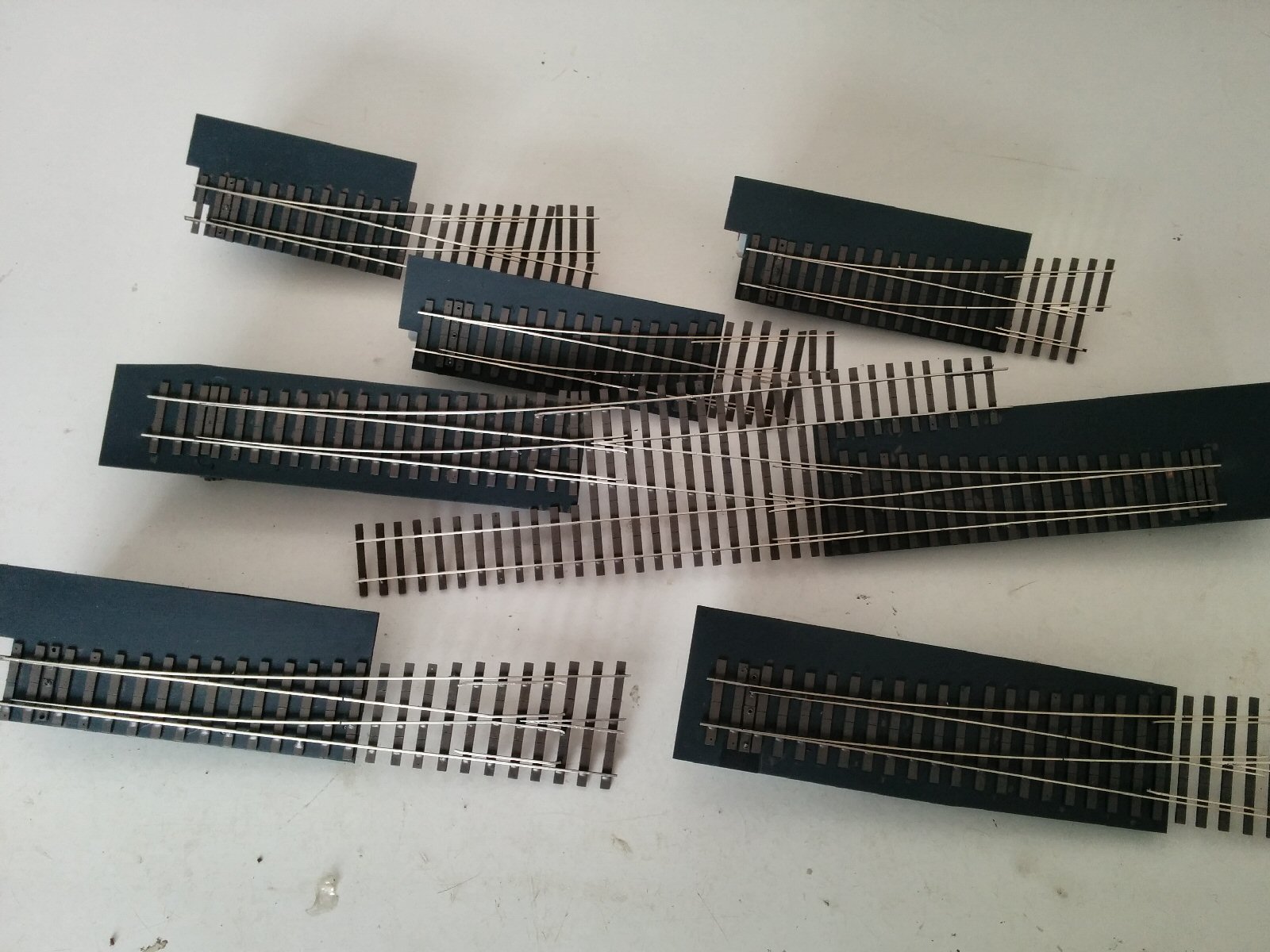
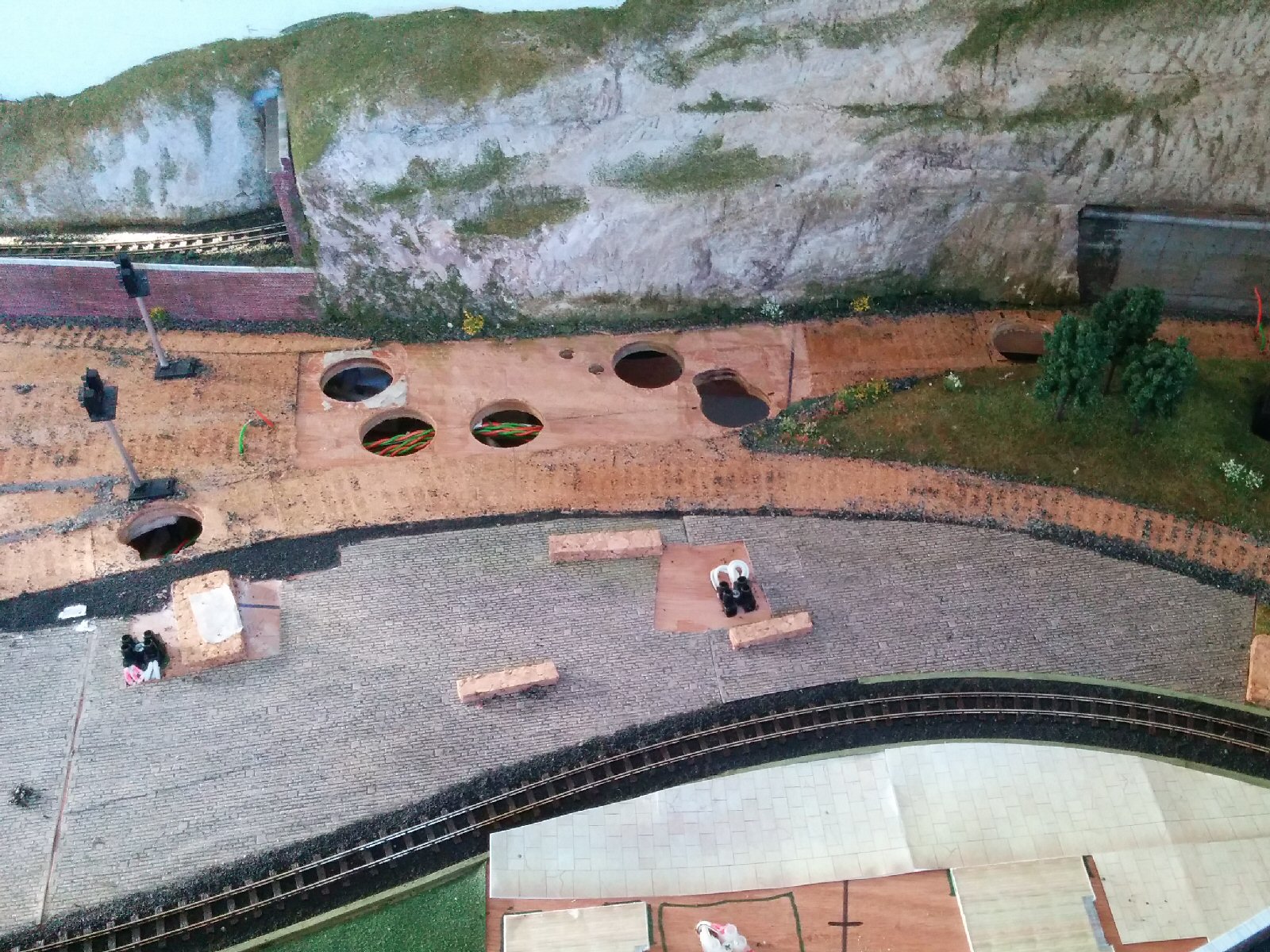
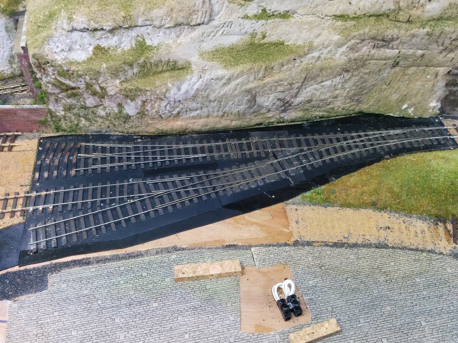
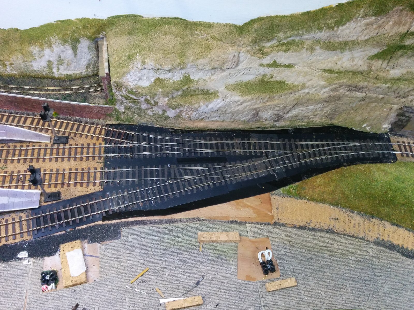
To make the job of mounting the new points on the layout easier, I’m experimenting with a method of attaching the point motor directly to the point, allowing the whole assembly to just be dropped into a suitable hole on the layout.

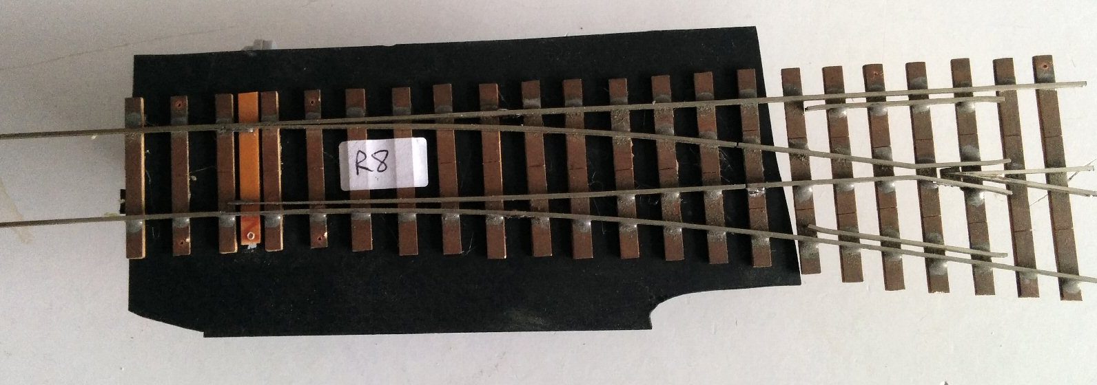
The first stage is to glue some thin plastic to the point sleepers – I used a bit of case from an old 8″ floppy disk (left over from the very early days of computing…):
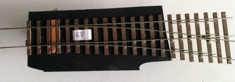
The plastic is wider than the hole will be, so should cover any gaps. There is a small gap in the plastic to allow the control wire to move the tie bar.

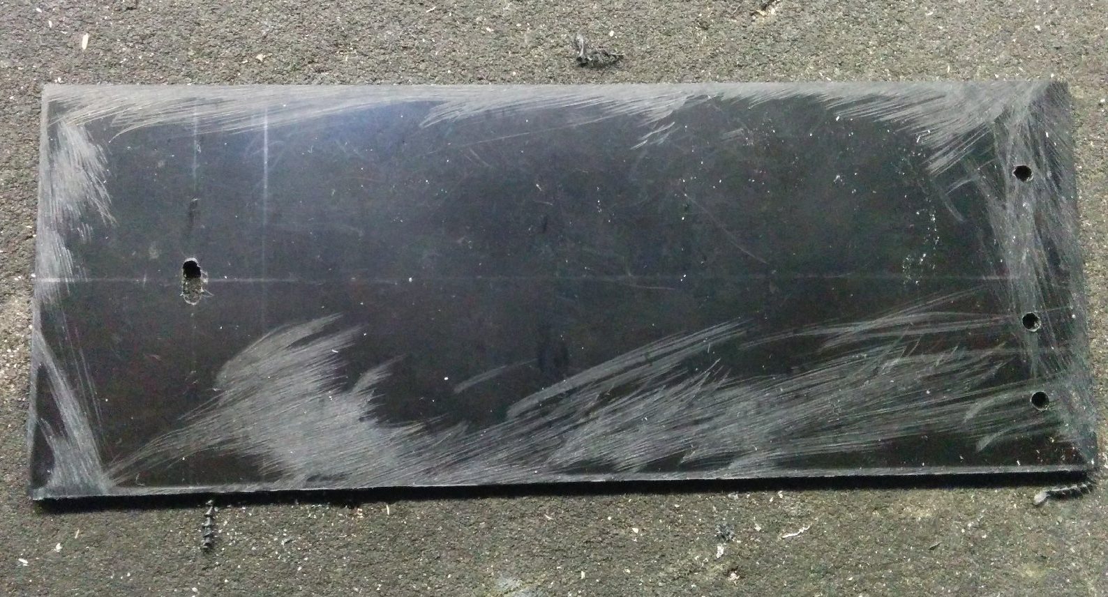
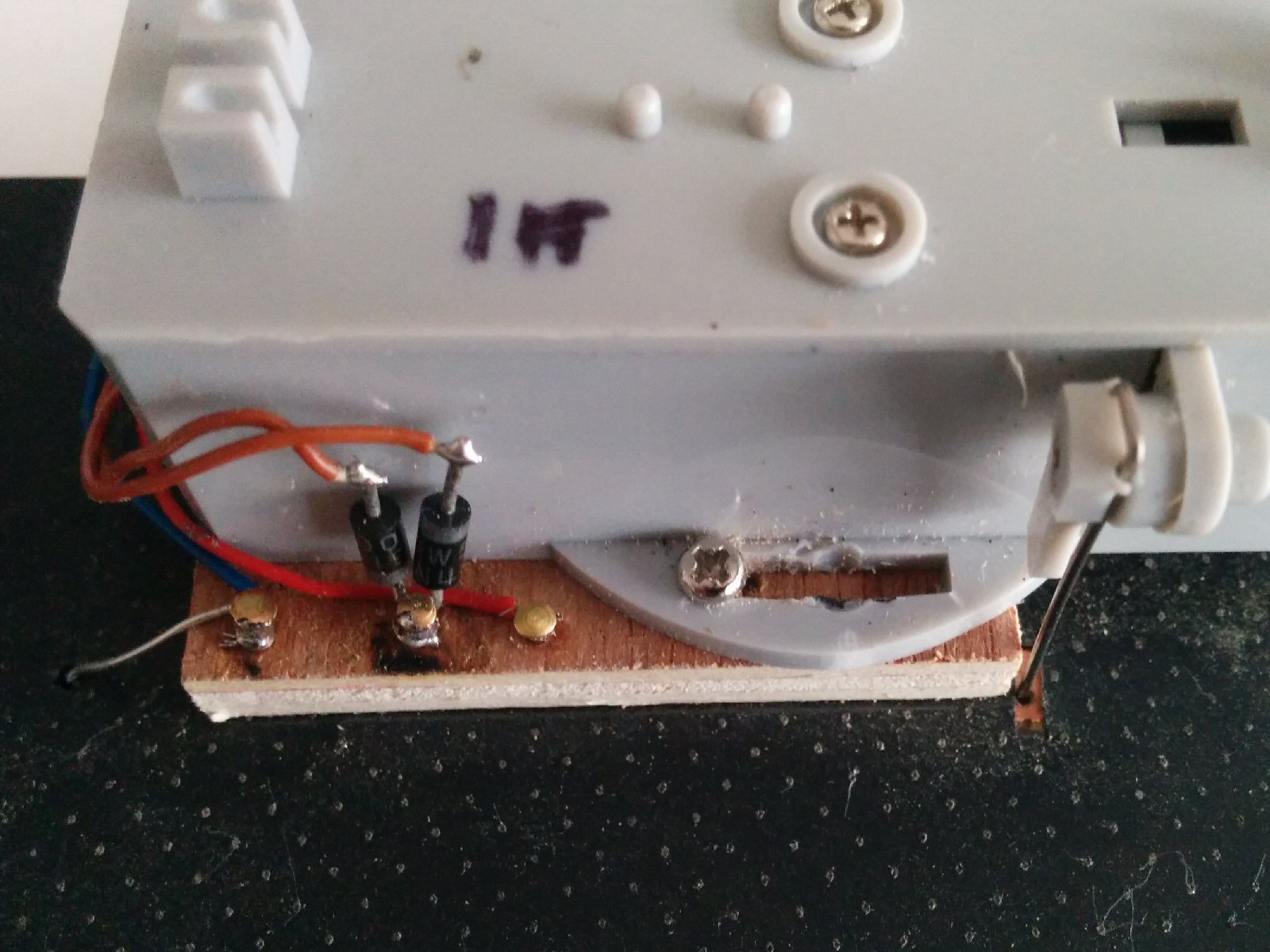
On the underside, a 38mm x 50mm piece of 6mm plywood is glued to the plastic, and the point motor (Conrad) screwed to this (1.5mm hole). The screws are too long for the plywood, so the excess are trimmed:
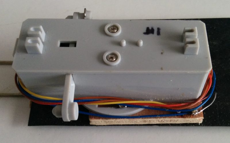
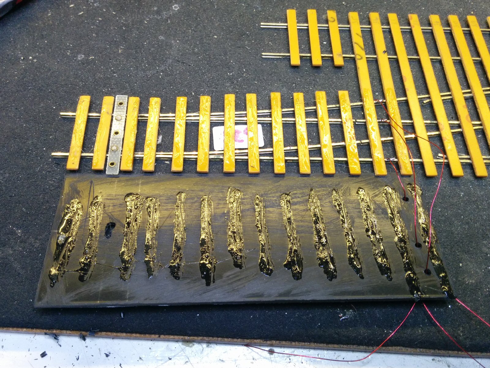
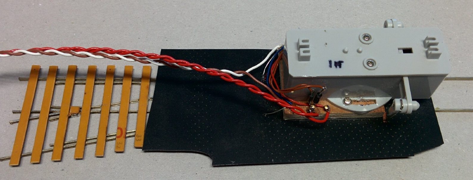
Wires from the point frog and rails are soldered to small pins in the wood. This allows a switch inside the point motor to change the frog polarity:
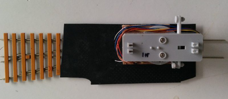
Two more pins allow a connection to the point motor itself:
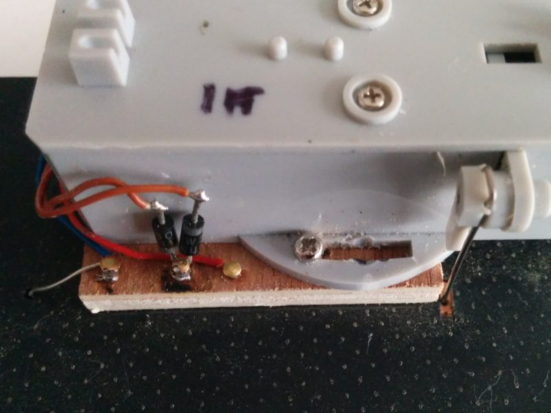
You can just see a spring steel wire on the right, which connects the moving arm of the point motor to the tie bar on the point.

Finally, wires are attached to the pins; the red ones will go to the point motor driver, the other pair to the track power:

Update 1
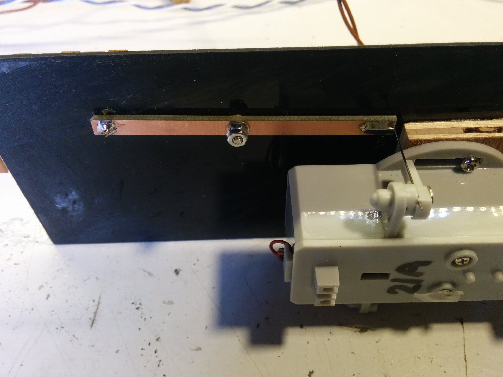
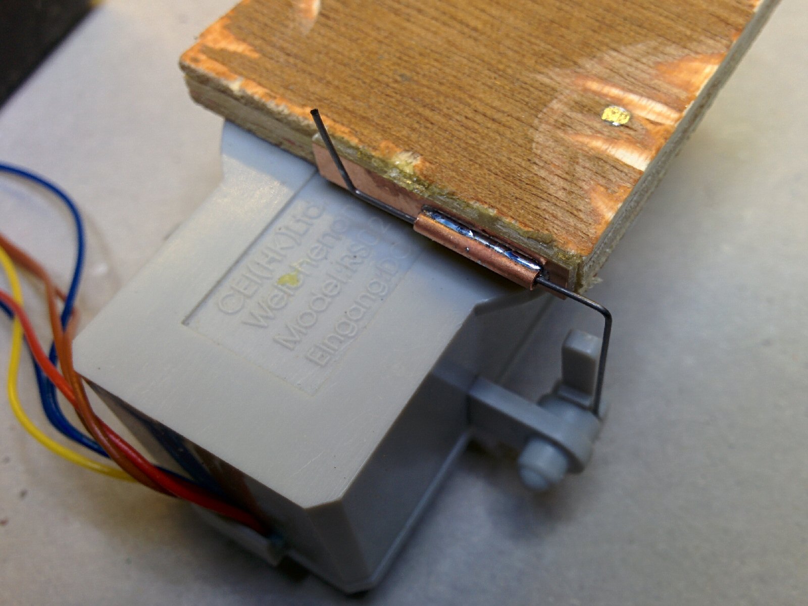
I’ve used a different arrangement for the spring steel wire on subsequent points:

This uses a much thinner wire (the thin wire supplied with the motor), constrained by the short copper tube under the motor. This produces enough force to move the point, but no so much that the point could be damaged should a problem occur.
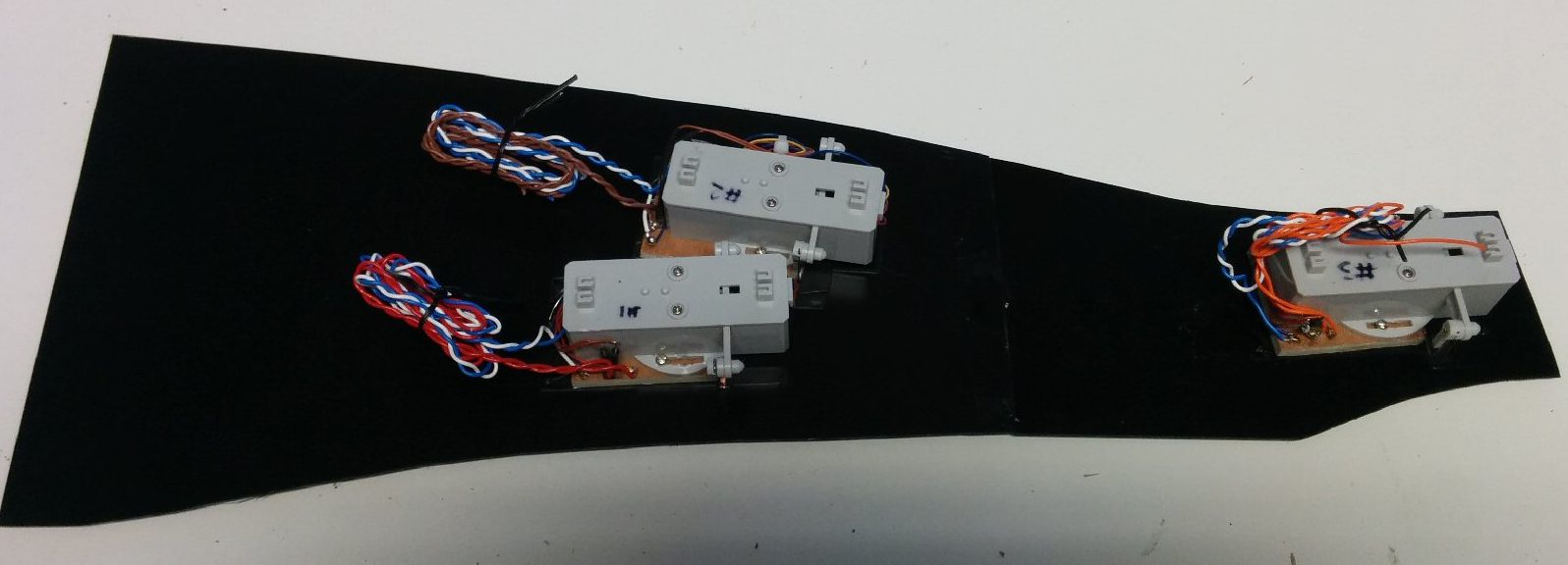
Update 2

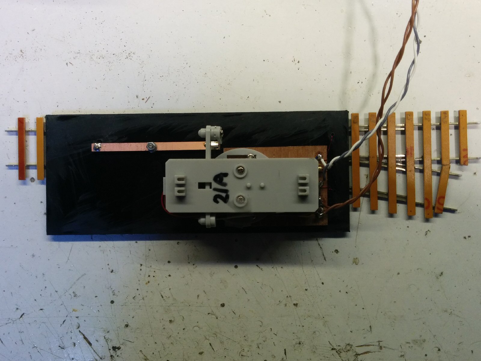
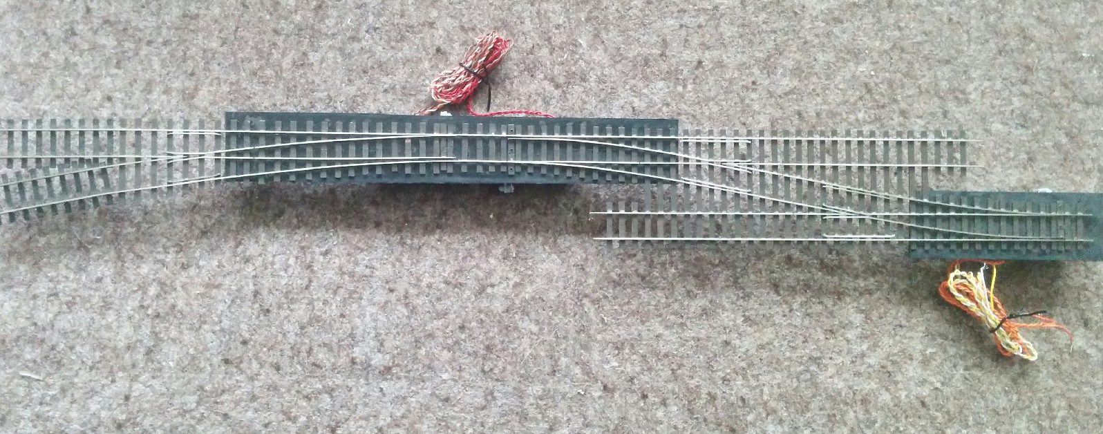
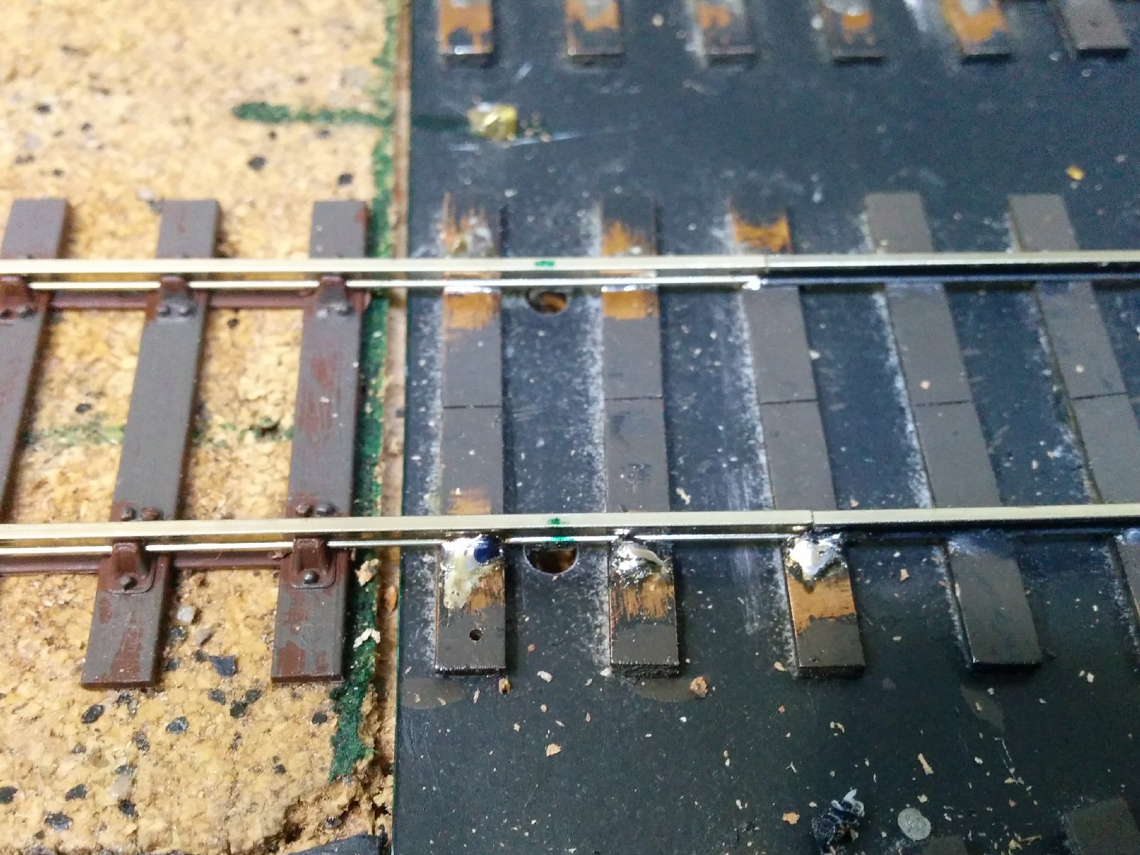
More point motors have now been fitted, and this photo shows a neater method for the construction and wiring. This motor is fitted a 6mm plywood base on 1.5mm black plasticard, with the point glued to the other side. This should match the height of the 1/16″ cork overlay, providing a constant top surface on the layout itself. Note that the wires are taken around the opposite side of the motor to the actuator wire.

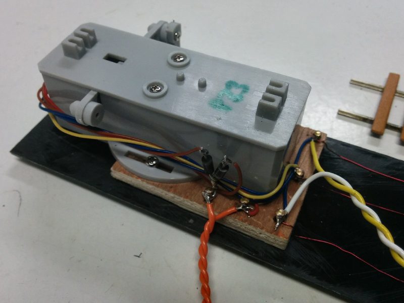
Note the thin red wires on the right that take the power to the point and frog.