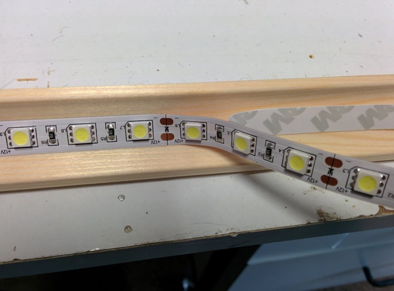
I finally got a chance to get some more wood and have constructed the last of the layout lights.These have all been made using “5050 Day White” LED strips stuck on to “Scotia Mouldings”…
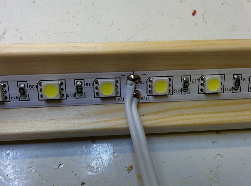
A wire is soldered onto the strip, normally somewhere in the middle. This goes through the a hole in the strip and into the wall:
Once attached to the wall, the wire is invisible:
Note that it’s the wall that’s wobbly, not the lighting strips!
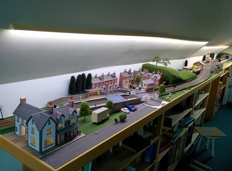
All the layout lights together take 42W of power – it’s a LOT of light for not much electricity. The next project will be a dimmer to turn them up and down as required.
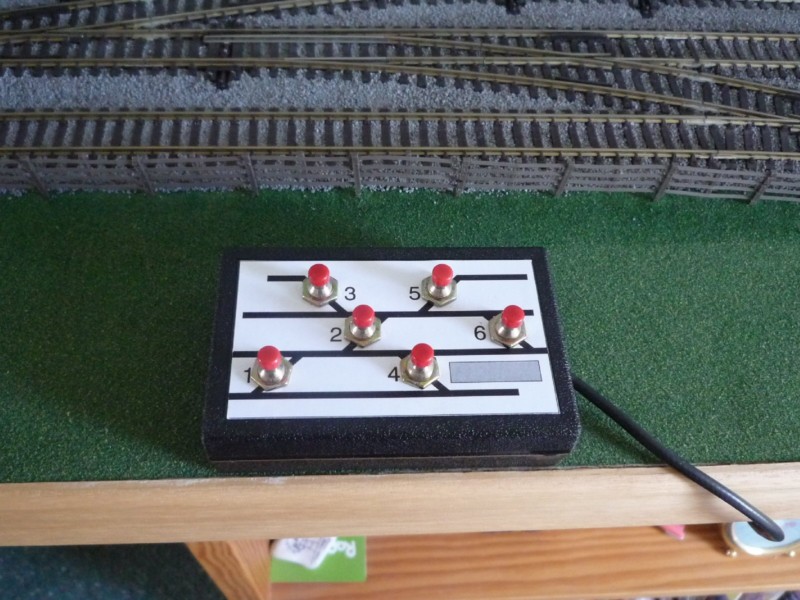
The railway power supply arrangements have been revised. As more electrical bits were added to the railway, the original solution was running out of ‘steam’.
The gold coloured box at the top is the main power supply for the layout. This will deliver up to 10A at 16v.
The silver unit on the left steps up the 16V to 24V to supply the point drivers; this has improved the point reliability now that the track has been ballasted.
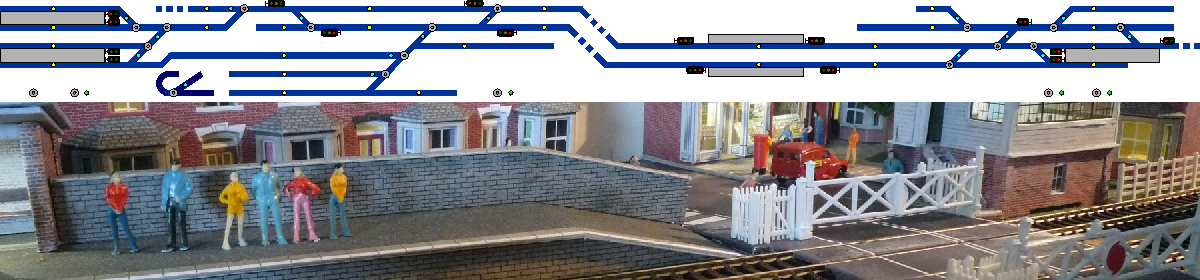
A small mimic panel has been added to the ‘Country’ end of the layout to simplify controlling the points at that end.
As there were a couple of spare inputs on the control board for this, I also took the opportunity to enhance the TOTI (Train on Track Indicator) circuits at this end.
For our club exhibition layout, there was a requirement that a short or fault in one section of the layout didn’t stop the entire layout operating. Initially, this would be done by having four power districts, each fed from their own booster.
As this would have increased the cabling, connectors and overall cost of the layout, alternative approaches were investigated, initially using the old trick of wiring a 12V lamp in series with each track feed.
Typical PTC Fuse
However, with modern components, a simpler approach is possible using PTC (Positive Temperature Coefficient) resettable fuses. They are sometimes called a Polyfuse or a Polyswitch.
These are low cost (20p) two terminal devices whose resistance increases dramatically as their temperature rises.
This has the effect of limiting the current under short circuit conditions. When the short is removed and the device is allowed to cool down, normal operation resumes.
A typical device, which we use for our 00 gauge layout, is the Bourns MF-RO50 device. The ‘cold’ resistance of this device is around 0.5 ohm, and the ‘tripped’ current when a short occurs is around 0.5A.
Other gauge layouts would need larger (or smaller devices).
These devices are also very useful for protecting various DC power feeds from short circuits.
Typical Connection
Power Feed
This shows the basic track connections for the PTC fuses. Within reason, the shorter each track section, the more protection will be provided.
MERG NB1B Booster Modification
When a short occurs, the initial current is limited by the booster, the layout wiring and the cold resistance of the PTC fuse (around 0.5 ohm for the MF-RO50). This current (peaking around 8A) is sufficient to trip an unmodified MERG NB1B booster, which defeats the whole point of the block protection.
However, if C5 on the NB1B is increased to around 220nF, LK2 is removed and the booster is set for 10A output, a short on any individual track will not cause the booster to trip. For this to work reliably, the power supply feeding the booster also needs to be capable of delivering the maximum short circuit current, albeit only for periods.
The NB1B current limiter (when mounted on a heatsink) is more than capable of limiting the current for the 200mS or so that the PTC fuse takes to warm up.
Monitoring
If an indication of a fault is required, a LED (with a diode and series resistor) can be wired across each PTC fuse. This will only be lit when a short or other fault occurs.
The other method is to touch the PTC fuse – it will be too hot to touch under sustained fault conditions.
Testing
Whilst in theory the current available from the MF-RO50 is insufficient to allow any DCC 00 gauge loco to operate, in reality, it works with the largest modern 00 loco we have tried – even with the sound wound up to the maximum. Empirical tests would suggest that this is because the loco current peaks are too short to increase the PTC temperature significantly.
Long multiple units are not a problem for our layout either, as the maximum length of track in any protected section is less than 4 feet and the power for a long train will be taken from multiple sections.
Note that if a short is sustained for a long period of time, then it can be up to 30 seconds before the device cools down enough to restore full power.
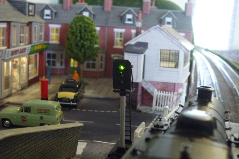
The CANSIG firmware provides automatic signal control for MERG CBUS systems. The firmware can drive Semaphore or Multiple Aspect Colour Light signals, and can support multiple events and routing to control each signal aspect.
Each CANSIG module can control up to four signals; these may be two aspect (or semaphore) signals, three aspect signals or four aspect signals. CANSIG can also support two ‘routed’ signals which will have different aspects depending on a ‘route’ setting – this would normally be set from a point position. Routed signals can also display a ‘feather on’ or ‘feather off’ indicator to show the route set.
CANSIG has six Non-Volatile (NV) parameters that control its operation; these are configured with the MERG FCU program. The FCU is also used to configure the events used to control the signals.
The software works with the MERG CANACC8 or CANLED64 boards. It will also work with the FLIM IO range of boards.
CANSIG has several different operational modes. Some examples are shown here:
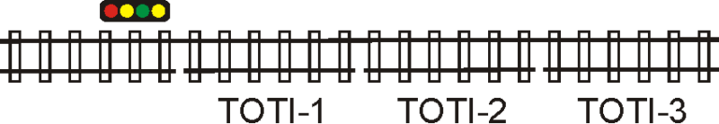
Plain Track, full TOTI Indication.
Configure the events as follows:
TOTI-1 -> Red A On
TOTI-2 -> Yellow A On
TOTI-3 -> D-Yellow A On
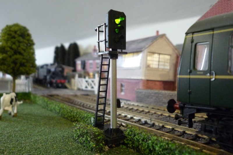
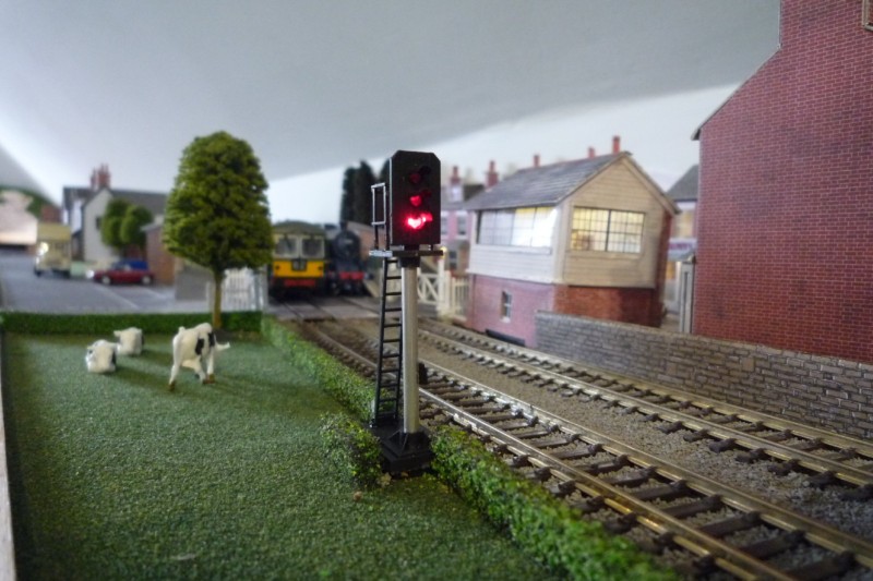
With no trains on the track, the signal will be Green. When the train reaches the TOTI-1 section, the signal will change to Red. When the train reaches the TOTI-2 section, the signal will change to Yellow. When the train reaches the TOTI-3 section, the signal will change to Double-Yellow. When all the TOTI sections indicate clear, the signal will change back to Green.
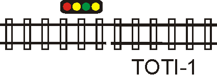
Incomplete TOTI indications
This mode can be used if there are insufficient TOTI sections for full signal aspect control.
Configure a single event as follows:
TOTI-1 -> Red A On
Also configure Red-Green Timer Mode to 10 and Yellow-Green Timer Mode to 15.
With no trains on the track, the signal will be Green. When the train reaches the TOTI-1 section, the signal will change to Red. After it passes this section, the TOTI-1 section will be inactive, and the signal will change to Yellow for 10 seconds, then change to Double-Yellow for a further 15 seconds. Whilst a timer is active, if any events arrive that specifically change the signal aspect, timer mode is automatically cancelled.
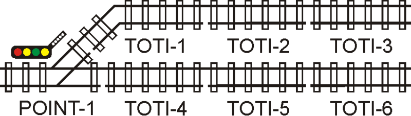
Simple Junction
This example shows the use of CANSIG with a simple junction.
Configure events as follows:
POINT-1 -> Signal 1 D-Yellow D/Alt On
TOTI-1 -> Signal 2 Red A On
TOTI-2 -> Signal 2 Yellow A On
TOTI-3 -> Signal 2 D-Yellow A On
TOTI-4 -> Signal 1 Red A On
TOTI-5 -> Signal 1 Yellow A On
TOTI-6 -> Signal 1 D-Yellow A On
With no trains on the track, the signal will be Green. If the point is set, the feather will light, and TOTI-1, TOTI-2 and TOTI-3 will control the signal aspect. If the point is clear, TOTI-4, TOTI-5 and TOTI-6 will control the signal aspect.
For full details and other examples, see the CANSIG Operation documentation (pdf), updated 21-Apr-13
The CANTOTI firmware is an extension of the CANACE8C v2g firmware and is designed to run on the MERG CANACE8C board. FlimConfig V14510 or later is required to configure the CANTOTI firmware.
Whilst the firmware is primarily designed to be used with TOTI (Train On Track Indicator) hardware, it is also suitable for monitoring other inputs, particularly if inversion or input conditioning is required.
Unlike previous versions of CANACE8C firmware, this code samples each input every 10mS, and will generate an event when each input is the same state for more than a configured number of samples.
Each input can be optionally inverted to allow for an “Active High” input.
To allow for noisy signals being connected to the CANTOTI, optional delays can be enabled on an input by input basis.
If “Delayed input” is enabled for an input, the input must be ON for at least the “On time” before an ON event is generated, and must be OFF for at least the “Off time” before an OFF event is generated.
The “On time” and “Off time” are set in units of 10mS, with a minimum time of 10mS and
a maximum time of 2540mS.
If “Delayed input” is not enabled for an input, the input must be ON for two 10mS samples before an ON event is generated, and must be OFF for two 10mS samples before an OFF event is generated.
The “Extended Configuration” value is not currently used; ensure this is set to 0 for
future upgrade compatibility.
The current CANTOTI firmware defaults to an input “On time” of 100mS and a “Off Time” of 500mS.
In addition, there is a build for the CANACE8C itself. This has the standard CANACE8C module ID, and defaults to to an input “On time” of 10mS and a “Off Time” of 10mS.
A wide variety of circuits can be used to detect trains. One of the simplest is this one:
This is for a DCC layout only; the diodes would be connected in series with the DCC feed to the track to be monitored. This requires an opamp with ground referenced inputs such as a LM324, and can easily be powered from the track itself.
I’m using three prototype DCC-TOTI boards (designed by Trevor Stockhill), each attached to a CANACE8C running the CANTOTI firmware:
These PCB’s are available from MERG as ‘DCC ToTI 8 PCB Part Number: 968‘.